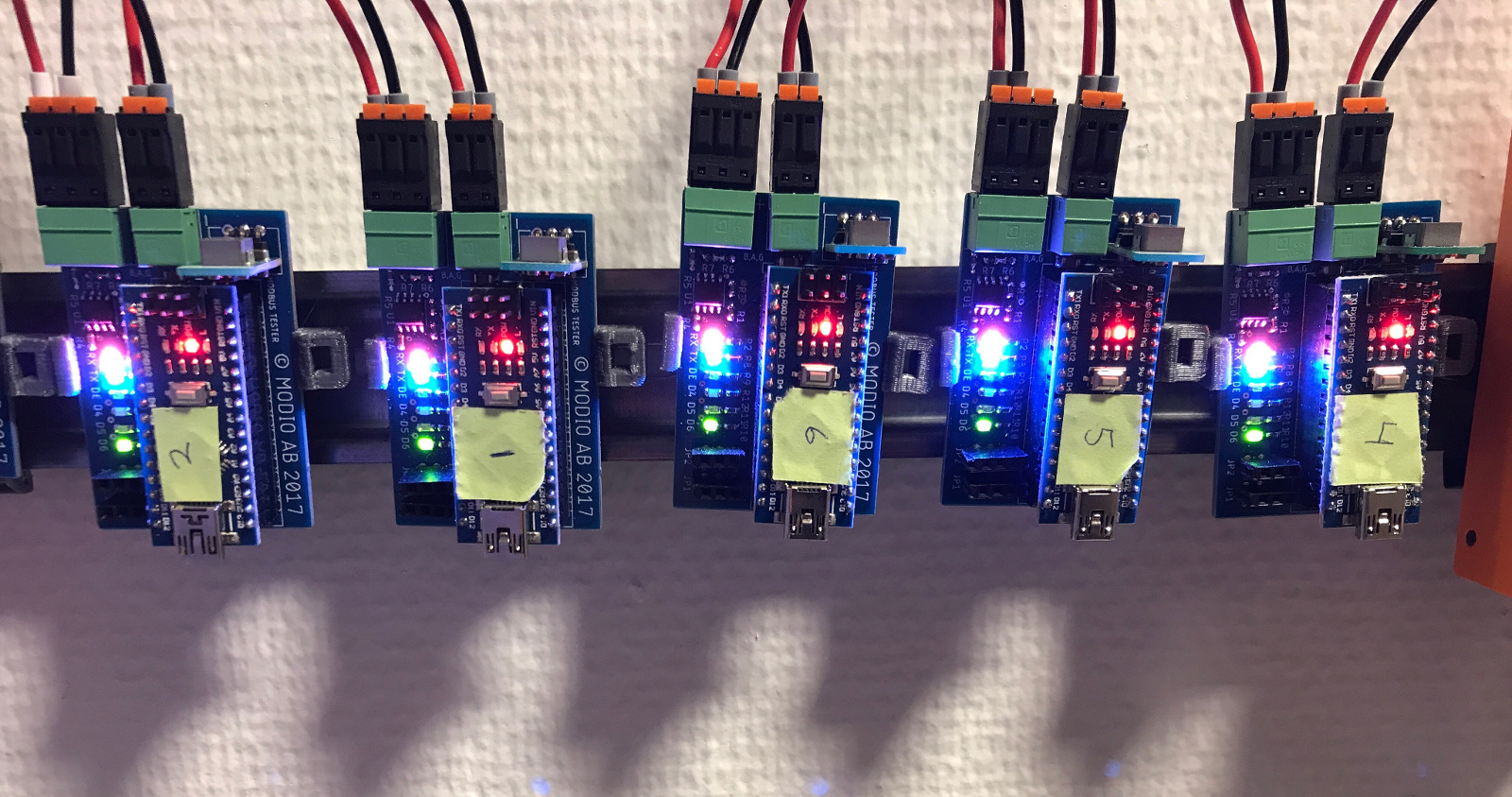
Modbus tester hardware
At modio, we use the communication protocol Modbus a lot. This is used for communicating between most of our equipment. While I think this protocol is mostly great, we have for some time experienced issues with timeouts because of specific systems that fail to read once in a while. This problem will only arise with one specific USB to serial converter that is used in some of our installations with older hardware. On top of this, most of the time it is fine, like the problem suddenly vanished. For me as an engineer, such problems are the worst, as there is no way to confirm that a certain hardware is non faulty without finding the cause of the problem.
What we know from experience is that the problem only exist if there are several units connected to the same USB to serial converter. This means that we could set up a test system to run and analyze, hopefully being able to find a trigger for the problem.
Hardware
For the above mentioned test, some testing hardware is needed. While I could go and buy nine expensive regulators or controllers that supports Modbus to use, they are not very flexible and may become unusable for this test if I'm unlucky. The quick and easy method is to build something myself. This way I can make it as flexible as I want and I will know in what way it will respond to commands.
The go-to method for these types of hardware is, for me at least, a microcontroller development board called Arduino nano. A simple device was built around this Arduino with a RS-232 to RS-485 IC (MAX485) to communicate with the microcontroller's built in serial interface and the RS-485 line that our Modbus devices use.
As the first prototype was needed immediately to start testing, I only implemented basic functionality, not much more. I built the testing device as a holder for the Arduino board, with added serial converter (232 - 485), some indicator LEDs and a pair of i/o pins for sensor reading or something similar in the future. In the picture below, the layout is seen.

Using the Arduino board, much of the peripherals needed for the MCU are already accounted for and need not to be worried about - more time for the rest of the design!
I did want to be able to see most of the circuit at all time, so most of the components are not placed under the Arduino board. This way it is obvious what suddenly makes that burning smell when you turn power the wrong way around or something (this happened). With this in mind, I'm happy to say that the final prototype design is within half of the 100 by 100 mm frame, the magical and optimal size for cost reasons.
The board is actually only 37 x 55 mm big, which means that it can be panelized to get two boards in one 100 x 100 mm frame, getting two for the price of one in the future. If only I could make it just about 7 mm narrower, I could produce four pcs in the same dimension frame, meaning half the current price, or 1/4 of the lowest possible price for a non-panelized board. Unfortunately, it was not possible with the time on hand.
I thought the testing device should be somewhat compatible with our other devices, regarding for example power supply. It uses the same keyed connector and 24 VDC power, but it should be polarity protected like the rest of our equipment in the future (I could use a diode bridge here).
The 24 VDC is converted down to 5 VDC with a switching regulator, giving up to 5 W of power. As the microcontroller only uses about 0.01 W to 0.02 W and the MAX485 only 0.003 W, most of the power usage goes through indicator LEDs. These LEDs should use about 0.1 to 0.2 W together. This means that any peripherals connected to this testing device should be able to use up to roughly 4 W of power without too much trouble. I'm thinking a small motor or actuator maybe?
Apart for the power connector, there is one RS-485 connector (same as our other devices because reasons). The connector is keyed anf has three pins. The MAX485 IC is used to convert the Arduino board's 232 to 485 and is connected between this terminal and the Arduino.
Also, there are two analog/digital inputs that can be used as digital outputs as well (the two i/o pins I mentioned earlier). The layout of these pins is compatible with standard RC servos with signal, V+, GND hint hint.
Software
I used the modbus library yaMBSiavr for communication and a simple data array for writable and readable holding registers. Holding registers can be used to control LEDs or the two outputs if needed. This part is expandable with for example advanced control loops or other system implementations that could be needed in the future. For now, I think only being able to write and read modbus holding registers in enough.
Result
I have now mounted the testing devices in our lab with a DIN-rail mount I made a CAD drawing of and 3D-printed. Testing began immediately. All good so far.

By: A. Hultman
